 First post of 2025, time for a new build! The PiDP-10 kit is the latest classic computing offering from Oscar Vermeulen at Obsolescence Guaranteed and the follow-up to his PiDP-8 and PiDP11 kits. I purchased and received the kit back in August last year, but then with the Florida hurricanes, getting super busy at work in the fall, and then the holidays and year-end, I finally just found some free time this past weekend to actually build it!
After ordering the kit last summer, I bought a new 4gb Raspberry Pi 5 (now the most powerful Pi in my collection) to run it along with a 64gb microSD (imaged with the latest RasPi OS, Debian 12 Bookworm), and downloaded the PiDP-10 software onto it. Then it sat in its box until this past weekend when I started on the build. As I’ve come to expect, Oscar’s kits are just incredible and each iteration has gotten better. No more painting switches or mounting wood blocks like the PiDP-8, or zip-tying switches to keep them straight during soldering like the PiDP-11. Other than the slight kludge of still needing to insert a piece of cardboard between the RasPi and the PCB, it’s a pretty straightforward assembly.
-
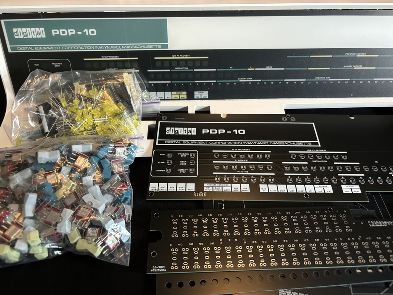
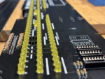
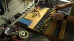
- kit parts
-
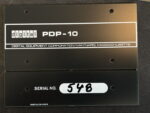
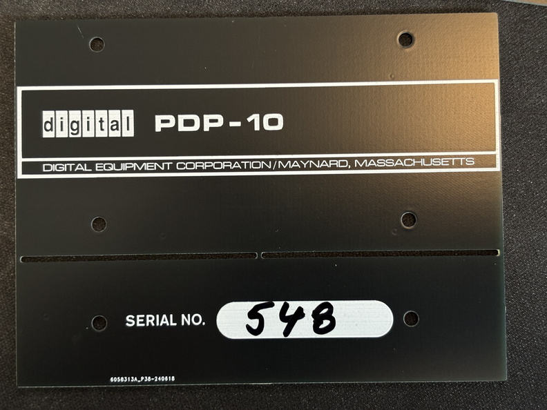
- serial number 548
-

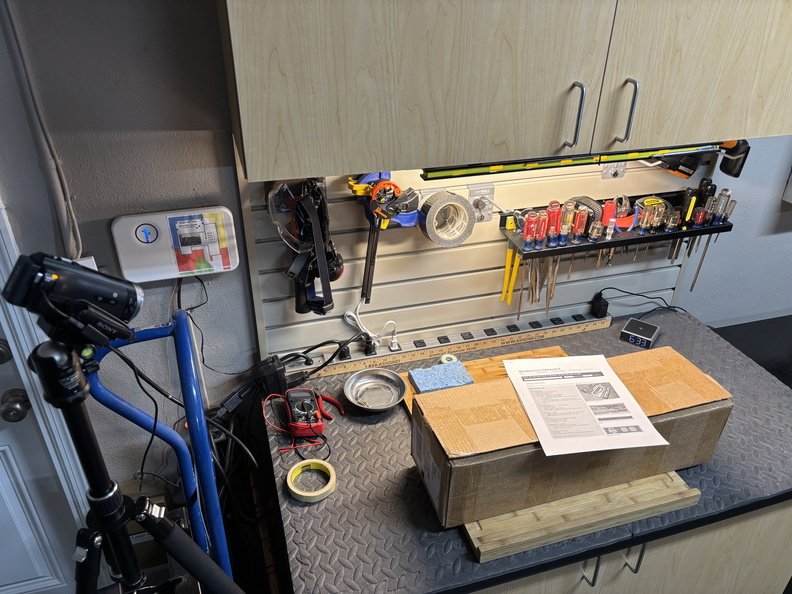
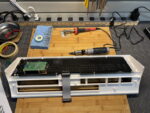
- workbench setup
It’s been almost three and a half years since my last kit build (the Altair-Duino 8800) and I quickly realized my eyes are not what they used to be (getting older sucks). I wear glasses now so I can read my computer screens and these circuit boards have so many tiny little holes so close together! 😀 I fell back into the routine of soldering pretty well, but early on ended up accidentally filling a hole before inserting a resistor so I had to re-learn how to use the soldering braid to clear it (and I ended up needing to use the braid several more times during the build, fixing mistakes caused by my poor eyesight).
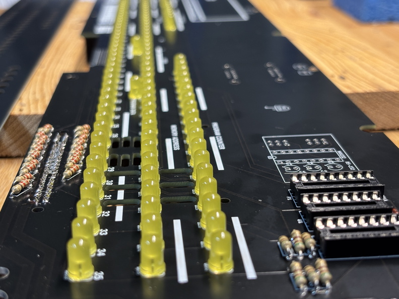
-
- installing 126 LEDs
-

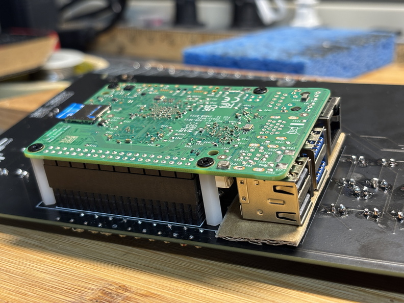
- RasPi mounted on PCB
-
- initial boot test

-
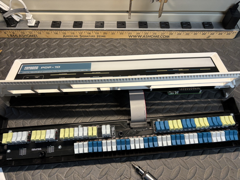
- installing LED PCB into upper case

-
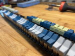
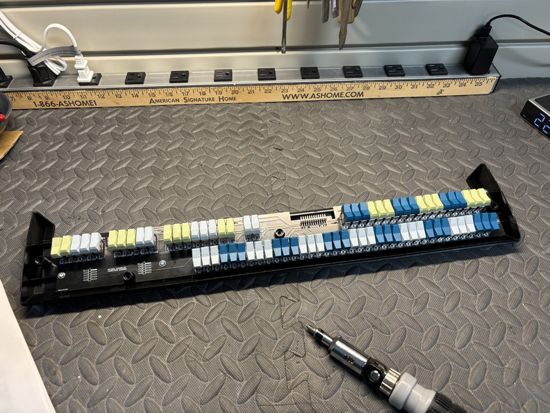
- installing 74 switches

-
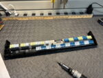
- installing switch PCB into lower case
-

- final case assembly
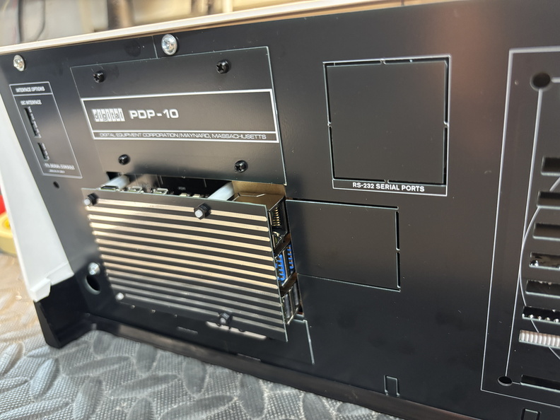
-

- RasPi and back panel
The full build took me just about 9 hours, three sessions split over two days. Here’s the obligatory timelapse video (and more photos from the build can be found here):
Some of that time was correcting my own soldering mistakes. After soldering in all the LEDs and pin headers (to connect the LED and switch PCBs), you attach the Pi and boot it to run a test script that allows you to confirm all the LEDs are working and the switch resistors are working. During the test I found a few LEDs not working and a single switch that also wasn’t functional. It took me a while to identify the issues (again, bad eyesight) and re-solder in the affected components but eventually had everything working and was able to proceed with the rest of the kit. After final assembly, I was pleased to find no other soldering issues (and considering each of the 74 switches was 4 solder joints, that’s not too shabby!) and everything was working as expected.
In case anyone was wondering, here’s the final soldering tally:
- PiDP-8: 370 (9 years ago!)
- PiDP-11: 380
- Altair-Duino: 586
- PiDP-10: 696 (whew!)
I had a great time assembling this latest kit. Now I need to find some time to play around with it! And since it’s got that powerful Raspberry Pi 5 in it, it might be time to revisit my old RetroPie setup.
Here’s the “family” photo: