 Hey, just so you know ... this post is now about 2 years and 7 months old. Please keep that in mind as it very well may contain broken links and/or outdated information.
 It’s been over two years since my last classic computer kit build and I was getting that itch to add more blinkenlights to my collection. Chris Davis’ Altair-Duino kit has been on my radar since last December when I saw it on episode #797 of Steve Gibson’s Security Now! podcast (which also introduced me Oscar Vermeulen’s excellent PiDP-8 and PiDP-11 kits) and I decided it was finally time to pull the trigger.
I went with the Standard kit over the Pro due to its smaller footprint (more flat instead of the boxier acrylic case) and, though the VT100 emulation calls back to my days as a VAX lab monitor in college, I probably wouldn’t really use it that much. The kit actually arrived the last week of July but I just recently had some time to sit down and build it in an afternoon.
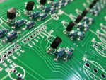
Like Oscar’s kits, the quality of Chris’ Altair-Duino kit is amazing. The parts arrived well packaged and organized and the instructions were clear and easy to follow. I’m no stranger to soldering resistors, LEDs, and switches by now, but I’m still no expert and even if this had been my first kit I feel like it would have been a straightforward exercise.
-

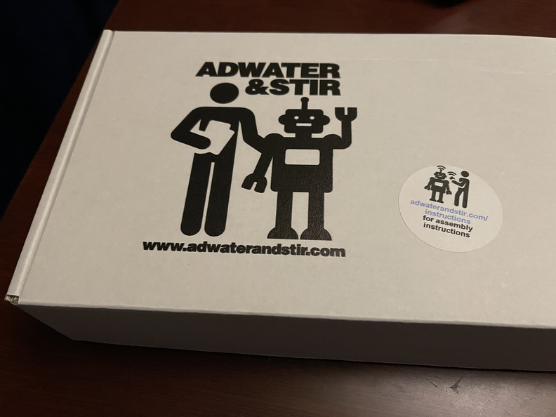
- the box
-
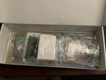
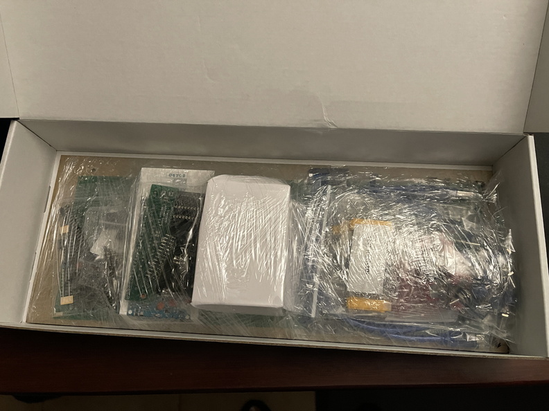
- parts – packagedparts packaging
-

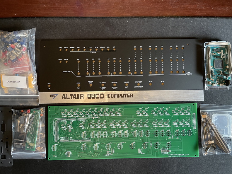
- parts – unboxed
-
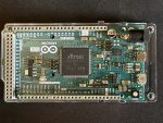
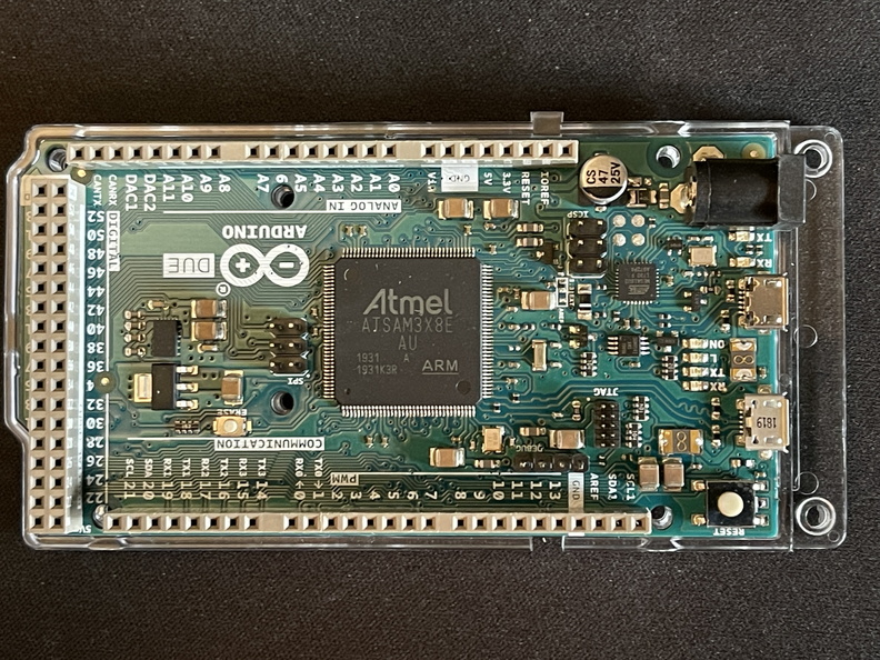
- Arduino Due
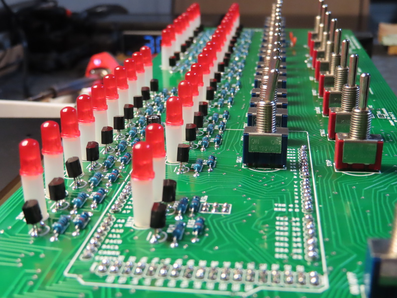
In just about 5 hours I had soldered 75 resistors, 36 transistors, 8 capacitors, 117 pin headers, 25 switches, 36 LEDs, and assorted other components for the expansion board for a grand total of about 586 solder joints (200 more than the PiDP-11!).
-
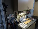
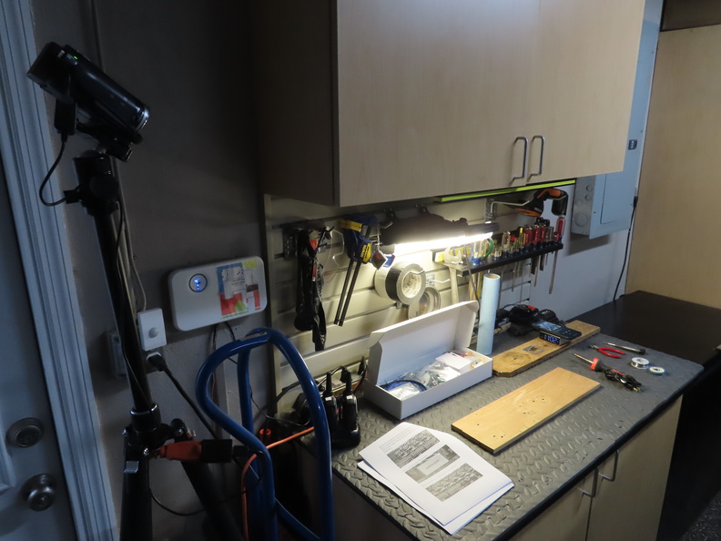
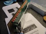
- assembly workbench setup
-
- resistors and transistors

-
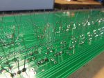
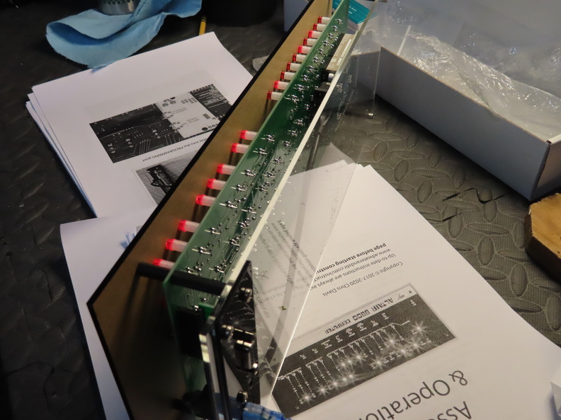
- soldered leads

-

- switches and LEDs
-
- expansion board

-

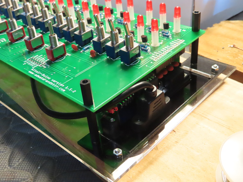
- rear panel and expansion board attached
-
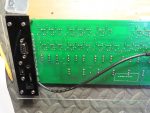
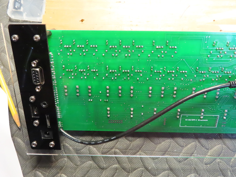
- rear panel, with expansion board
-
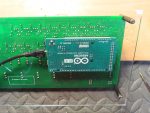
- rear panel, showing Arduino Due

After the initial build, I had two problems to troubleshoot:
- first, the AUX1 switch didn’t seem to do anything; I re-soldered the three pins and that fixed the issue
- second, after a few times of plugging in the Altair-Duino (using the power supply connected to the expansion board instead of a USB cable), I found that sometimes there would be no power and I’d have to jiggle the connector just right to get it to power on. I re-soldered the three pins on the power connector on the expansion board and that seemed to fix it!
So only two soldering issues out of 500+ … not too shabby. 🙂
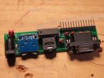
Unlike the Raspberry Pi-based kits I’ve built before, the Arduino Due in this kit comes pre-configured with David Hansel’s Altair 8800 Simulator (and a microSD card with more classic software) so it boots up right away without needing to install anything. Also unlike the Pi, the Due has no networking jack so I purchased a pre-programmed WiFi module (the ESP-01S) which I soldered onto the mainboard. So while normally you connect the Altair-Duino to a PC via USB cable and then connect via a serial connection (ex. COM3, 115200 baud), the WiFi module allowed me to connect the Altair-Duino to my local wireless network and then telnet in with PuTTY. Another difference here is the RasPis are running Debian Linux with the PDP emulator on top of that. With the Altair-Duino, the only “operating system” is the simulator, so there’s no underlying Linux shell to connect to.
-
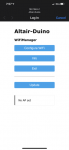
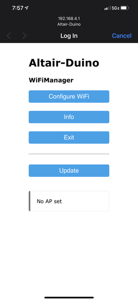
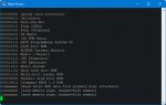
- ESP-01S captive portal for WiFi setup
-
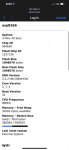
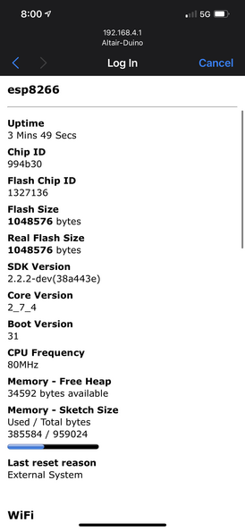
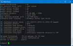
- ESP-01S info
-
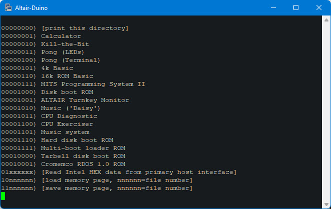
- built-in software
-
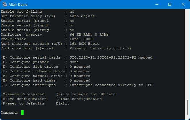
- configuration menu
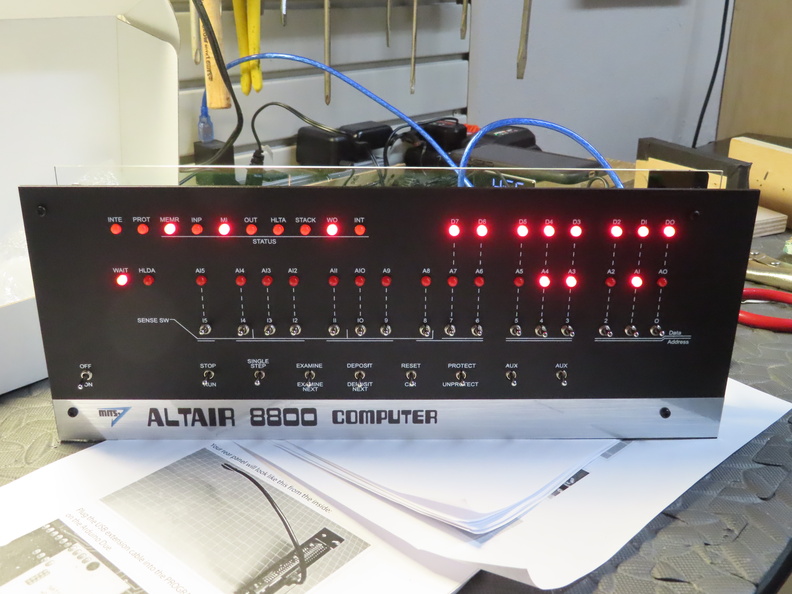
My only issue with the kit so far is that the LEDs are bright. This might be because there’s not really a case for the Standard kit, it’s basically an open sandwich of the faceplate, circuit board, and clear plexiglass back. There’s no plastic in front of the LEDs like with the PiDP-11 or PiDP-8 so the LEDs are unfiltered and a little glaring.
-
- completed kit – rear angle
-
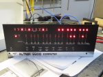
- completed kit – front
-
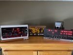
- PiDP-11, PiDP-8, Altair-Duino

I still need to take some time to read the simulator documentation, play around with some of the classic software, and maybe even toggle in a program, but for now I’ve got another sharp-looking blinkenlights machine along with my PDPs. Here’s the timelapse video: