 Hey, just so you know ... this post is now about 6 years and 11 months old. Please keep that in mind as it very well may contain broken links and/or outdated information.
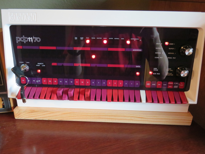 Three and a half years ago I built my PiDP-8 kit and it’s been happily blinking away on my desk ever since (it also runs my Pi-Hole). Earlier this year, on episode #698 of Steve Gibson’s Security Now! podcast, Steve mentioned that Oscar Vermeulen had come out with a new kit, the PiDP-11! I loved the experience of building the PiDP-8 and the quality of the final product so I immediately signed up on the mailing list to be in Oscar’s next batch of orders.
A week later I received (and submitted) my order form. While I was waiting for the kit to arrive, I picked up a Raspberry Pi 3 B+ kit and 32gb SD card. Following the instructions in Step #1, I prepped the SD card with Raspbian (Jessie Lite) and downloaded and installed the PiDP-11 software. Since the RPi 3 B+ is a lot more powerful than the RPi 1 B+ in my PiDP-8, I decided to consolidate and move my Pi-Hole and Retro-Pie installations onto it as well. With the Pi ready to go, I just needed the kit …
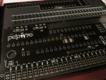
After another week and a half the kit was delivered. Unlike the PiDP-8’s wooden case, the PiDP-11 has a nice white plastic case, and the switches are also colored plastic, so no need to paint them! The silk-screened front panel and PCB are beautiful, Oscar does incredible work on these kits.
-
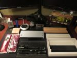
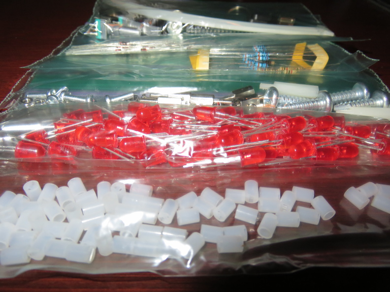
- all the parts, unboxed

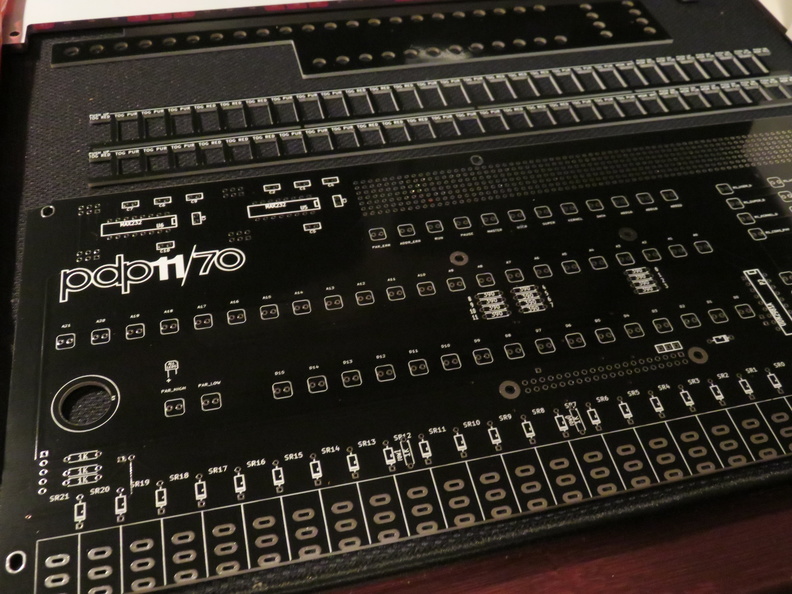
-
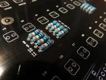
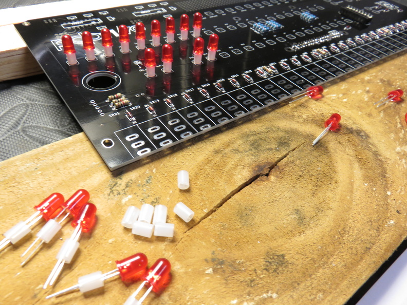
- the PCB
-

- I organized the little parts into baggies
Unfortunately it was another two weeks before I had a solid chunk of time to actually assemble the kit. I still had all of the necessary supplies from last time (soldering iron, solder, desoldering braid, multimeter, side cutters, etc.) so I dove right in and started soldering.
-
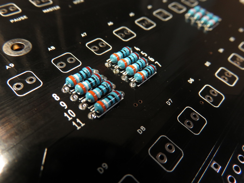
- resistors
-
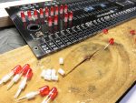
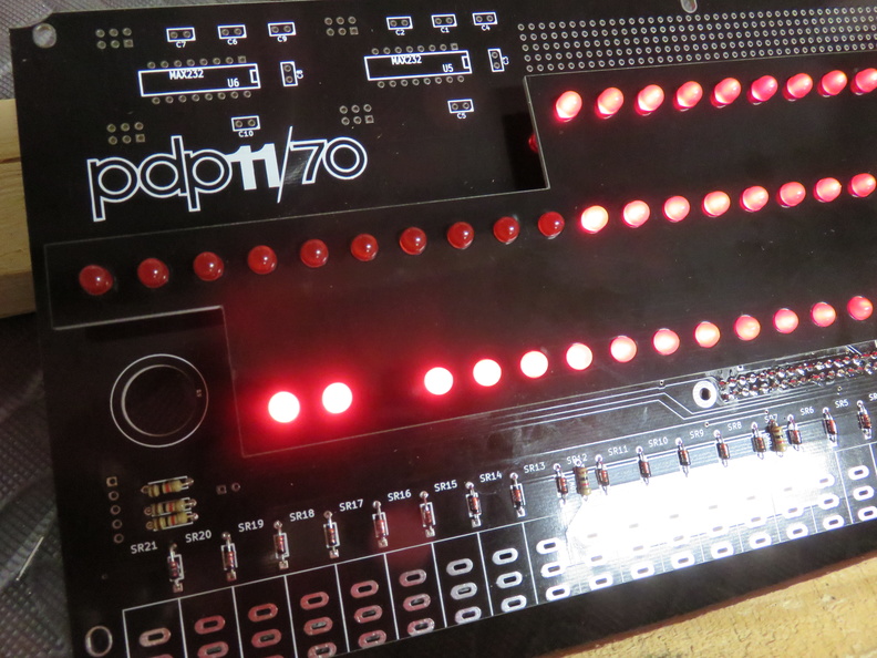
- soldering LEDs
-
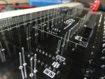
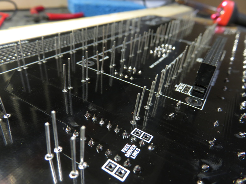
- lots of pins to snip!
-
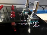
- rotary encoders; notice the LED mask too
-

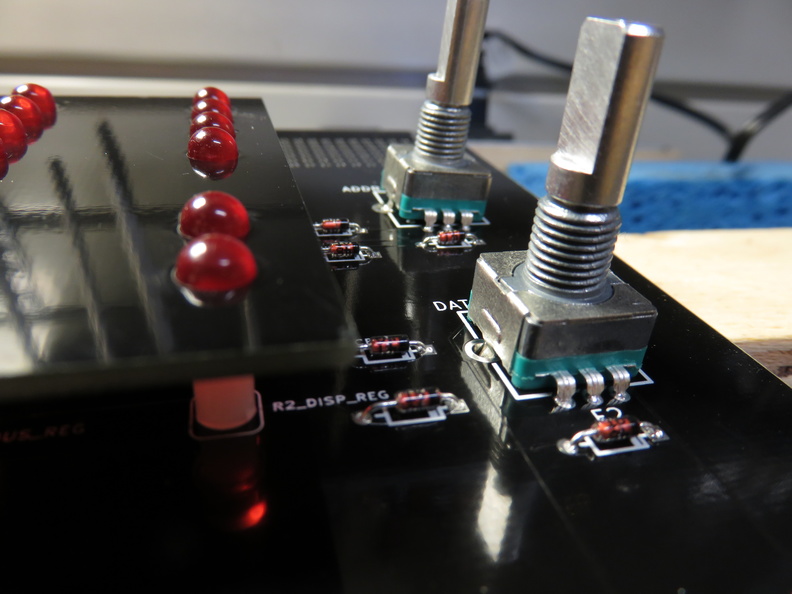
- preparing to solder the switches
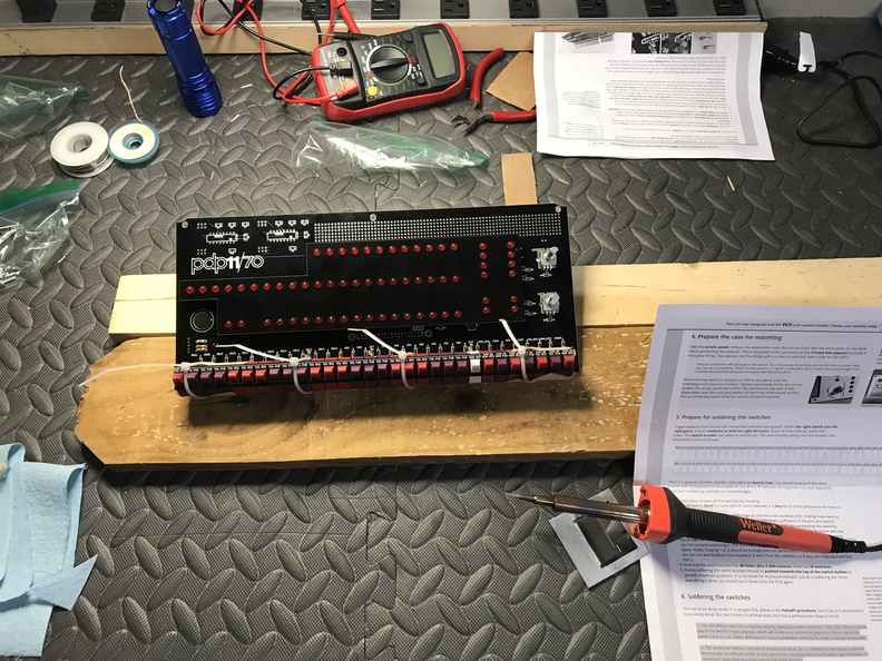
It took me just over 5 hours start-to-finish. Here’s the entire process compressed to 10 minutes (and you can find more photos of my build here):
I did have some minor problems during assembly:
- with my multimeter, I found one bad LED that wouldn’t power on; luckily there were spares included (and I found it before I soldered it in!).
- during testing (Step #3), LEDs 12-21 didn’t power on; I traced (heh) this down to two bad solder joints on the GPIO riser, which I corrected and fixed the problem. whew!
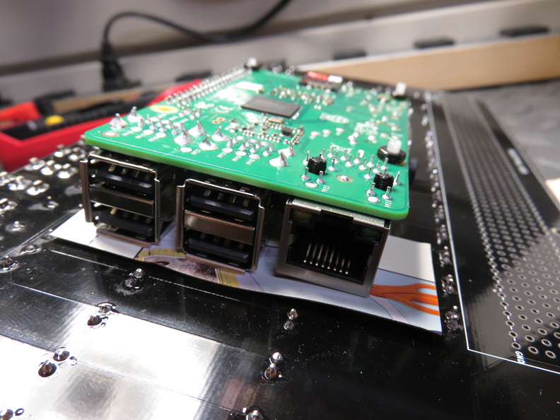
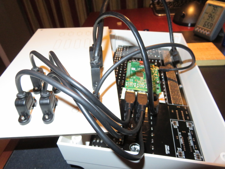
- you have to install a thin piece of cardboard between the USB ports of the Pi and the PCB (to prevent the metal ports from shorting the solder joints right below them; hopefully this isn’t a fire hazard or anything.
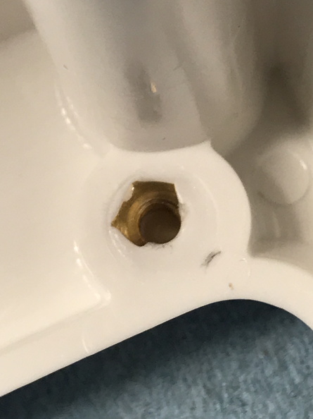
- one of the metal inserts in the case was slightly covered by the extruded plastic which made it hard to thread in the brass hex spacer, but I managed to get it in without damaging anything.
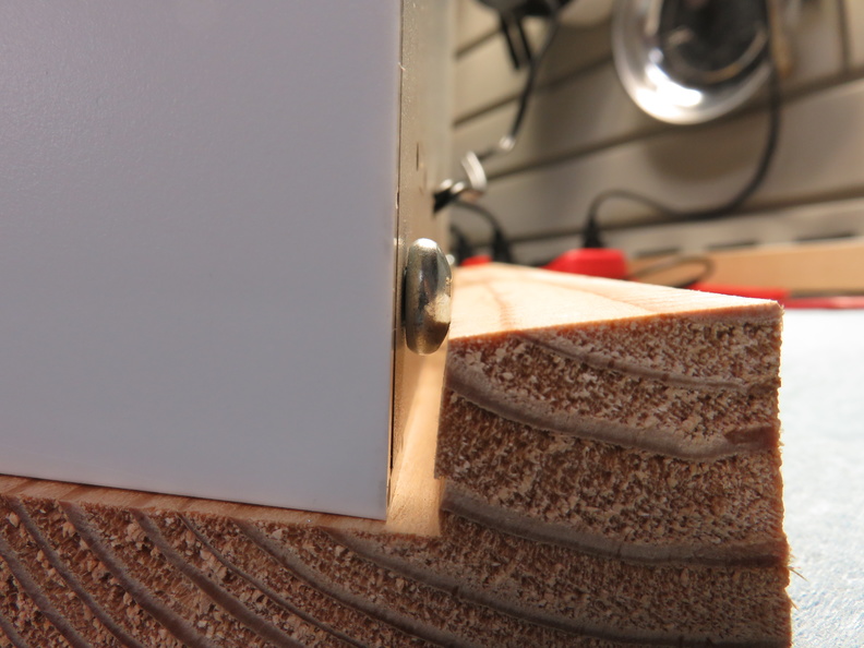
- the big screws holding the rear panel on the case don’t clear the top of the wooden stand, so the case won’t slide all the way back (doesn’t seem to be a big deal though).
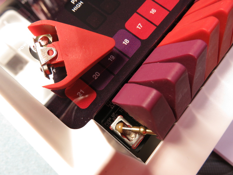
After all of that I was so close to being done without any major issues, but after closing up the back, powering up, and then testing the switches, switch 21 broke off! For now I’ve got it taped to switch 20 so it stays in place. I wrote to Oscar and found out I wasn’t the only one who had a problem like that so it might have been a bad production run. He’s sending me a replacement free of charge, so I’ll have to open up the case, remove the broken switch, and solder in the new one (testing my de-soldering skills!) once it arrives.
-
- row of LEDs not lit
-

- cardboard between Pi and solder joints
-
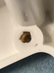
- plastic-covered screw in case
-

- rear panel screw prevents flush mount against wood stand
-
- oh no! a broken switch!
Altogether I soldered 37 diodes, 18 resistors, the GPIO riser and chip socket, 64 LEDs, 2 rotary encoders, and 30 switches for a grand total of 380 solder joints! That’s a mere 10 more than the PiDP-8 kit (fewer LEDs, but more diodes and switch pins).
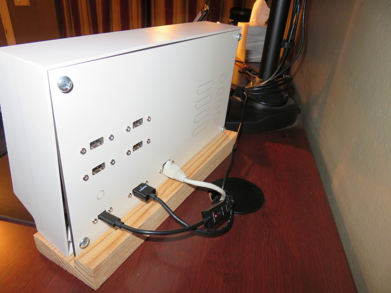
Another nice touch on this new kit is the pre-cut ports in the back panel … no more custom drilling! I went with the AdaFruit panel connectors (like this one) with the knowledge some cutting and cable stress might be involved. It was definitely difficult getting everything into the case. Originally I left the bottom portion of the back panel slightly open a) to not have the HDMI and ethernet connectors push on the PCB, and b) figured that it would help with air flow. This meant the case sat even more forward on the wood stand, but it seemed to be stable. But then I realized I was having HDMI signal issues and the address encoder LEDs were flickering. I think the stress/pressure of all those cables inside the case was too much, so I reverted to the open back for now (which is really too bad because the back panel really looked nice with all those ports!).
-
- back panel connectors; that’s a lot of cables to squish in there!
-

- nice looking back panel. but notice the gap at the bottom
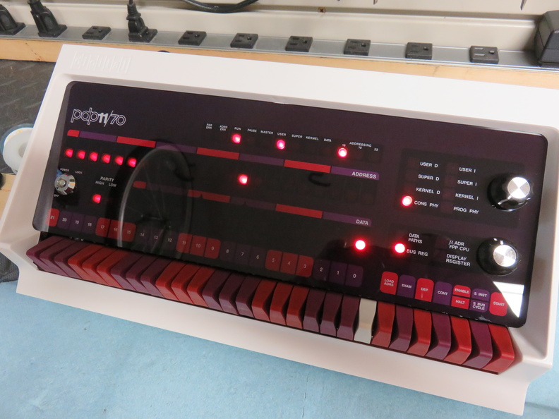
Despite those little problems, the finished product looks fantastic:
-
- completed PiDP-11
-
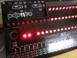
- PiDP-8 and PiDP-11 (side view)

-
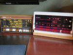
- PiDP-8 and PiDP-11

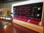
So now on my desk I’ve got a little PDP-11/70 replica that is also blocking ads on my network and allows me to do some retro gaming. It’s so cool looking, and I built it (mostly) myself!
What’s next for Oscar? Sounds like maybe the PDP-10? Whatever it is, I’m sure it’ll be amazing. Keep up the great work!
My replacement switch from Oscar arrived today. I found out my desoldering skills are not as good as my soldering skills as it took me a long time to get the broken switch off of the PCB. But I managed to get the old one removed and the new one installed so now the kit is officially complete.
My next kit build: the Altair-Duino. Coming soon!
Here’s the Altair-Duino!
I noticed the other day that some LEDs were out on my PiDP-11, specifically columns 2, 14, and the entire right-hand column controlled by the two radial dials.
Using Oscar’s schematics and circuit board diagrams I was able to trace the most likely problem pins on the GPIO header. After a little resoldering of pins 7 and 22, I had working LEDs again!
Oh man, Oscar’s PiDP10 kit is now available. I might just have to get and build one!
I bought one. 🙂 Now to find the time to assemble it …
The PiDP-10 is alive!